Description
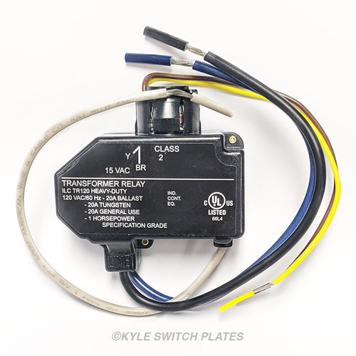
Pass & Seymour 1070B mechanical latching relay has three low voltage leads coming out of the top and two line voltage leads coming out of the bottom. Reliable field-tested switching circuitry that provide central or local control of lighting loads.
Features
- rated 20 amp, 120/277 volt
- 24VAC/24VDC control
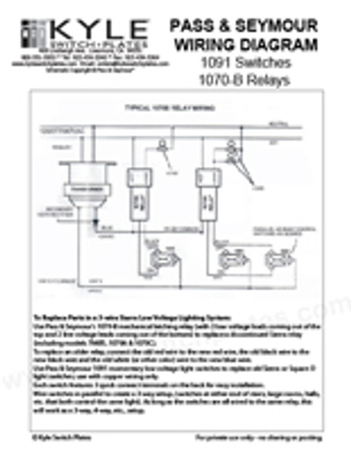
- includes wiring diagram as connected to P&S low voltage switches
- replaces Pass & Seymour/Sierra 1070A, 1070C, 7201 and 7048S relays
- operates on momentary impulse
- 1.176" W x 3.156" H; .818" diameter cylinder; white plastic cap can be removed for installation
- mounts in standard 1/2" KO through noise suppressing nylon ring
- insert the mounting gasket into knock out opening before inserting relay
- 3 low voltage leads - one red "ON", one black "OFF", one blue "COMMON"
- Class 2 momentary, draws .520 mA
- conforms to NEMA WD-1 and WD-6
- 5-1/2" (140mm) #22 AWG leads for easy wiring.
- split coil design energies ON coil to close line contacts and OFF coil to open contacts
- low voltage leads: pre-stripped type SRIR #22 stranded tinned wire thermoplastic insulation 5.5" (140mm) long
- line voltage leads: #12-19 stranded copper wire type T-1/32 INS Black 6"
- can be installed in any position
- CSA and UL Listed for 120/277V; also CSA listed for 347VAC
Wiring Tip: In general, to replace an older 3-wire relay, from the low voltage side of the relay connect the old red wire to the new red wire (ON), the old black or blue wire (OFF) to the new black wire and the old white (or other color) wire (COMMON) to the new blue wire. Be sure to check your connections as there was no color standard, so it is possible your old wire colors are different. Per the included wiring diagram from Pass & Seymour: the red from the relay goes to the ON side of the switch, the black wire goes to the OFF side of the switch and the blue wire (common) goes to the transformer.
3-Way Switches: Wire switches in parallel to create a three way switch setup, (switches at either end of stairs, large rooms, halls, etc. that both control the same light). As long as the switches are all wired to the same relay, this will work as a 3-way, 4-way, etc., setup.
Tips When Replacing Failed Relays
To avoid damaging a new relay, we recommend replacing any vintage switches connected to the relay including any switches at the light location as well as those in a master panel connected to the same relay. (Relays seldom fail after a short period because of a manufacturer defect; they would simply not work at all upon installation.) Try to determine why the old relay failed to prevent damaging the new one, too.
Relays typically only fail when contact is maintained on a switch. This includes a temperamental switch that sometimes gets stuck, or from holding down a switch on a relay that is starting to fail. Maintaining contact causes the relay to heat up: the internal parts will melt together and eventually freeze the relay in its last position (whether on or off).


