Use this GE low voltage lighting troubleshooting guide to track down which parts of your vintage General Electric low voltage wiring system need replacing. This guide also works with other 3-wire systems such as Sierra or Bryant.
Before beginning to troubleshoot a low voltage system, ensure that all light bulbs are in good working order in any fixtures (ceiling light, table lamp, etc.) on the circuit you are testing. Note: GE switches may be wired like 3-way or 4-way switches to control one light from two, three or more locations. When following the instructions, please pay attention to whether you think a switch was wired in parallel with other switches. When wired in parallel, all the same color wires on all switches in the series are connected together: the red wires all connect together, the black wires all connect together, and the white wires are connected.)
Which Parts Need to Be Replaced?
Use the chart below to narrow down which part of your GE system needs to be replaced to get the lights working again. Determine if you have a bad switch, relay or transformer, then order replacement GE parts here.


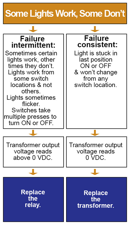
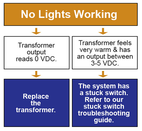
See the stuck switch troubleshooting guide here.
System Setup
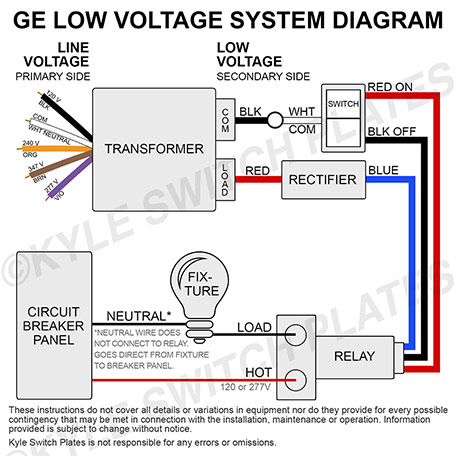
These instructions do not cover all details or variations in equipment nor do they provide for every possible contingency that may be met in connection with the installation, maintenance or operation.
Information provided is subject to change without notice.
Kyle Switch Plates is not responsible for any errors or omissions.
Remote Control Relays
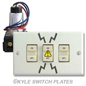
Bad Switch: If you can control the same relay from one switch location but not another, the switch is the problem, not the relay. In other words, if multiple light switches (for ex., several on one switch plate or those installed on two sides of a room) are connected to a one particular relay and at least one of the switches on that circuit can still turn the lights on and off, then any switch that cannot control the lights is broken. (Remember - this could be one or more switches.)
Bad Relay: If you only have a single switch connected to the relay, you can check to see if there is continuity through the relay using an ohmmeter. If the overhead light is supposed to be off (meaning that the relay switch is supposed to be open), but there is still continuity through the relay, then the relay probably has been overloaded and is defective.
If you don't have a meter, then you could also test your relay by removing the switch that is currently connected to it and putting in a working switch from another location. (Just be sure you are wiring it correctly.) If the new working switch doesn't work in the problem location, the relay likely is broken; if the lights do come on then the old switch was broken.
Buzzing Noise: If you can hear a loud buzz coming from your relay, this typically indicates a malfunction in either your relay or the switch connected to it.
First, be certain you don't have new switches mounted in old brackets. New GE switches are too large for the original brackets, although they can be forced in. This can result in a stuck switch due to the switch being pinched by the bracket.
Once you're certain you don't have new switches squished into old brackets, test which part is damaged (the switch or the relay). Do so by unwiring a switch that is working correctly in another room, then replace each switch connected to the buzzing relay until the buzz stops. (Or if that doesn't reveal it, perhaps there may be two switches that are stuck, so you would want to disconnect all the switches and test each individually.) If the relay no longer buzzes, then you know which switch was bad. If the relay still has a buzzing sound after testing all of the switches, then you know your relay is defective.
Larger Issue: To double-check whether just the relay needs replacing or whether a larger issue with your system exists, swap the relay into a different position on your electrical panel. If the problems follow the relay, then the relay is defective. If not, the issue is with something else in the system, such as a transformer, control board, or wiring setup.
Testing Switches
Disconnect the wiring between the relay and the switches. Connect a multimeter to the wiring coming out of the wall that had been connected to the switches. Check for shorts from common to ON or OFF. If there is a short, you know you have a bad switch or wire. These should always be open until a switch is pressed.
Testing Relays
Ensure you have a working light bulb in the light fixture.
Note: Relays are either in the ON or OFF position (which you can't tell by looking at them). Once installed you must push the light switch to have the relay change its state from either ON to OFF or OFF to ON.
First, ensure the relay is properly energized with 24VAC to the BLUE lead of the relay.
Shorting (tapping) the RED(ON) to the common of the 24VAC supply will turn the relay to the ON position. Check the line voltage side of the relay for continuity. It should be a short.
Shorting (tapping) the BLACK(OFF) to common of the power supply will cause the relay to change to the OFF position. Check the line voltage side of the relay for continuity. It should be open.
Switching back and forth should produce an audible click.
If you cannot produce these results you likely have a bad relay.
Tips When Replacing Failed Relays
To avoid damaging a new relay, we recommend replacing all vintage switches connected to the relay: this includes any switches at the light location as well as any switches in master panels connected to the same relay. (Relays seldom fail after a short period because of a manufacturer defect; they would simply not work at all upon installation. Try to determine why the old relay failed before risking damage to the new one, too.
Why Relays Fail
Relays typically fail when contact is maintained on a switch. This includes from a sticky, temperamental switch or from holding down a switch on a relay that is starting to fail. Maintaining contact causes the relay to heat up: the internal parts start to melt together and eventually will freeze the relay in its last position (whether on or off).
Other Reasons For Relay Failure
There are several situations that can cause a relay to fail, even a new one. Conditions that cause a constant flow of electricity will damage a low voltage relay:
- Painted, wallpapered, or broken plates might cause drag or pressure on switches causing them to stick or drag.
- Dusty or grimy locations such as kitchens or workshops can cause buildup on the switch potentially causing a slow response.
- New RS23X switches (black bordered housing) being forced into the smaller holes in an old stacked style strap. The new switches are slightly larger than the vintage rocker/teeter-totter switches, so they will pinch the housing causing the switch buttons to stick.
- Installing a standard line voltage switch (even temporarily) where a momentary switch is required. Line voltage switches provide a constant flow of electricity.
- Installing a new relay without replacing all connected switches. Be sure to check for a master panel switch wired in parallel to the light fixture, too. Typically something causes the old relay to fail, so be sure to test all the switches for the fixture (upstairs/downstairs, both ends of a hall, etc.) If the switch seems at all sticky or slow to respond, it may be time to replace it.
- Wiring that has been chewed by rodents or squirrels may cause cross wire shorts and odd behavior in the system.
Shop GE Remote Control Relays and Transformers.
Light Switches
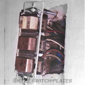
To check the wiring on your switches, override the switch at the wall for testing. To do this, simply remove and unhook the switch, then tap the common wire (usually white) to any of the low voltage button control wires. If doing this direct testing of each of the wires works (lights come on or turn off), the switch is either defective or the contacts on the switch need cleaning. (Gently wipe off the contacts with a clean cloth; do not use any cleansers as they can damage the delicate contacts.)
Take a meter and confirm continuity for each button press (meaning that the expected action - ON or OFF - occurs when you push the button). With the switch removed there should be continuity from common through each button once the button is pushed.
Transformers
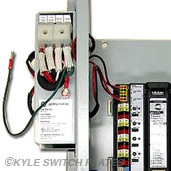
GE low voltage systems usually have one to many switches wired to a relay, and several relays connected to a transformer. If all relays and switches appear to be broken, then the transformer may be the issue.
Bad Transformer: If possible, take a working relay and switch and move them to the suspect transformer. If they still work, then all the switches and relays on the other circuit really were broken and need replacing (unless it is some sort of wiring issue - compare the setup to a known working setup). But if the working relay/switch set doesn't work in the new spot, then your transformer is likely the issue.
Test the Transformer: Disconnect the transformer from the panel and check the output to rule out wiring issues. Confirm the input voltage - either 120V or 277V - depending on the model. The normal output voltage with the load disconnected would be 25-29 V AC (nominal should be ~27.5 V with 120 V applied). This wider range allows for meter variation as well as variation in the line voltage.
If the voltage is between 3-5 VDC and the transformer feels warm or hot to the touch, the system has a stuck switch that is causing the transformer to heat up, so the switch needs to be removed. If the transformer reads 0 VDC, disconnect and wait for about 15 minutes. Reconnect it again and test the output voltage. If the voltage is still at 0 VDC, the transformer is bad and needs to be replaced. If it shows voltage (maybe 3-5 VDC), there is a stuck switch somewhere which caused the transformer to go into cool down mode, producing the 0 VDC found earlier.
Note that you can have many relays (20, 30, etc.) connected to a transformer, but you do not want to drive (turn on/off) more than 5 relays at the same time. When updating or fixing your system, just be sure you don't overload your transformer trying to control too many relays at once.
Q. After releasing a button that I push on my switch, the switch maintains continuity for about 15 seconds. This causes a delay before the lights either turn on or turn off. We have also burned out one transformer already. Is there a short?
A. You might have a stuck switch causing a short at a pilot light or locator light. To locate the problem switch, disconnect the white wire from all of the switches connected to the transformer. Measure the voltage at the transformer between the two low voltage wires. If it is 24V that proves the short is clear. Start connecting the switches back and test each one by measuring the voltage again. If there is a voltage drop that will indicate which switch is causing the short. Replace the switch with a new one and test again that the problem has been resolved. For more information about resolving a stuck switch problem see How To Fix a Stuck Switch in Low Voltage Lighting System.
Q. Can I use a 24VDC transformer with my GE system?
A. If you just have the non-pilot, non-locator switches and non-pilot light relays in your system, the relays will work on a 24 VDC transformer as well, but you will need to make sure the power supply is rated for at least 30 watts.
GE Rectifiers
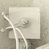
This is an old GE rectifier. This controller switch above the transformer is a rectifier. The old GE catalog says it recommends using one with all remote control installations. It can be replaced with this 3A rectifier diode that reduces the energy used by the relay coil. The action of the rectifier improves performance (faster switching) and affords greater protection to the system but you do not have to have it. Please note however that a rectifier is recommended when the system is using pilot light switches or locator switches because without the diode the switch light bulb will burn out in a few years. (The diode will increase the life of the locator light bulb as it will provide only half the energy supplied by the transformer (blocks the other half).) But if you bypass the rectifier the system will still work. The standard AC output is sin wave, but the rectifier just cuts off half of them (may be called a half wave AC). If the rectifier is broken the relay will stop working so we recommend replacing it with the rectifier diode or simply disconnecting it from your system.
Additional Tips
Visual Damage: Check to see if there is blackening on the parts or if there is a burnt smell. This simple check may quickly reveal which part is damaged and needs to be replaced.
How many relays can be controlled by a single switch?
GE recommends not exceeding 8 relays being controlled to the same switch in vintage systems because there is no sequencer: so when pressing the button, all relay coils are energized in same time. The current used is about 220 mA per relay, so having too many relays wired in parallel will drop the power voltage and the relays will not switch. If you need to control more than 8 relays, GE suggests upgrading to the new LightSweep systems. The new systems are sequencing the command to the relays with each receiving a 100 msec pulse to change state.
How can I find an electrician to work on my GE Low Voltage system?
GE low voltage systems are basically very simple but some electricians may feel intimidated if they are not familiar with them. Customers have had success by reading up on the information on our website in order to clearly explain what work needs to be done. You can do some simple testing then have the parts ready. Or you ask the electrician to do the simple testing then buy the parts and have them come back a second time. Ex. I tested my switch and relay. In one location I need a combo relay replaced along with the switch connected to it. In another location I just need the switch plate unit replaced. They are easy to replace and I have wiring diagrams. you might also try reaching out to electricians who have been in business a long time and who may have experience with these systems.
Note: Electricians unfamiliar with the system may suggest removing the whole system. However this involves opening up all the walls and running heavier wire between the switches and the light fixtures which can be very expensive. This is seldom the route taken as faster, easier, cheaper solutions are available to get the lights back on and working properly.
Which Low Voltage System or Brand?
Not sure which low voltage system you have? Identify Your Low Voltage Lighting Brand will help you figure it out and point you to the correct replacement parts.
Shop Low Voltage Lighting Replacement Parts for GE Lighting, Bryant, Sierra Electrical, Remcon, Pyramid, and Touch-Plate Lighting Controls.
