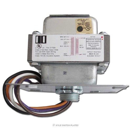
Description
Replace your old GE low voltage transformer with this updated heavy-duty model that converts 115A, 277V, 240V, 347V power for your 24-volt AC system. This versatile low volt transformer powers your remote control relays in a new or vintage low voltage lighting system as well as in other applications that require Class 2 power to actuate banks of relays and solenoid valves, or illuminate pilot lights or halogen lamps. Its universal electrical box cover can fit 3.25" to 4" octagon boxes or standard 4" square outlet boxes.
Features
Heavy Duty Transformer for GE Low Voltage Wiring
- Class 2 transformer replacement for General Electric RT1, RT2, RT3, and RT7 models
- frequency rated 50/60 Hz; 50 VA capacity, 16392-04
- input 120V/240V/277V/347V
- 24V output at 2.08A, 50 VA
- energy-limiting transformers require no external fusing
- low voltage connectors marked COM and LOAD; 6-32 screws for wrapping wires around
- 6" flexible leads for line voltage connections
- equipped with auto-resetting thermal protector
- easy mounting options in metal box: in panel, with 4" square junction box cover plate, or with 1/2" threaded conduit nipple
- Class 130 (B) insulation system
- for residential use in U.S. & Canadian homes
- US listed and CUL certified
- manufactured in USA
TIP: If your current transformer feels hot, there may be a stuck switch draining the power. Try checking all the switches to see if that frees up system and restores power.
Other applications: HVAC controls, home automation setups, irrigation panels, door and gate openers, machine controllers, etc.
Alternately, choose GE's dual power supply with a pair of 115V/277V transformers wired in parallel: GE Low Voltage Dual Transformer 115V 277V.
Installation
To install, use the correct wires per your low voltage wiring control system:
For 120 V, the connection would be to White & Black; all other wires (Orange, Violet, and Brown), should be capped with a wire nut or otherwise insulated. (To replace RT-1)
For 240 V, the connection would be to White & Orange; all other wires (Black, Violet, and Brown), should be capped with a wire nut or otherwise insulated. (To replace RT-3)
For 277 V, the connection would be White & Violet; all other wires (Black, Orange, and Brown), should be capped with a wire nut or otherwise insulated. (To replace RT-2)
For 347 V, the connection would be White & Brown; all other wires (Black, Orange, and Violet), should be capped with a wire nut or otherwise insulated. (To replace RT-7)
Shop low voltage replacement light switches, switch plates and power supplies at Hard to Find Low Voltage Replacement Parts.
Technical Notes
The transformer has a bimetallic auto-reset thermal protector connected in series with the secondary winding. If the winding temperature reaches the trip point (due to overload or short circuit), the element snaps open breaking the circuit. When the coil cools, the element snaps closed reestablishing the connection. This cycle will continue as long as the overload or short exists.
Under direct short circuit, the protector will cycle after 10-20 seconds. Initially, it may reset fairly quickly; however, if the short persists, the period between resets will increase.
Switching multiple relays simultaneously causes strain on transformers, so a very general recommendation is to only drive 5 relays maximum per transformer at the same time. However this really depends upon the power used by the fixtures as well as the length of the wires, so be sure to check with your electrician to confirm that your setup is configured safely. (Note: you can connect more relays as long as no more than 5 relays are turned on or off (actualized) at the same time.)
Switching multiple relays at the simultaneously causes strain on transformers.
Grounding: Generally, the transformer is grounded through the pipe nipple or outlet box cover plate when it's mounted to a metal box. If for some reason the transformer isn't mounted to a metal box, or the box is not grounded, a ground lead can be connected to one of the screws that holds the covers in place and that wire in turn connected to a grounding point. Ground wires should be green or green with a yellow stripe and be at least 14 AWG with crimp type connectors on the ends.


